
Intro
The idea here is to run a Rasberry Pi for as long as possible.
I got the idea after finding a couple of different Reddit posts where people were comparing the up-times of their Raspberry Pis. This is a fun, silly little project, and so far, it’s been showing me some engineering challenges that I didn’t expect.
A long time ago, I had purchased a specific module that allowed for dual power input into a Pi MoPI-Hat. I started to think about what it would take to engineer a way to run this thing for a minimum of two years. But I didn’t want it to only run (“Do Nothing”), It wasn’t until I got halfway through the project that I decided what this Raspberry Pi is going to run Doom, but we’ll touch on more on that a bit later.
Design
The first step in this project was to figure out how I was going to realistically accomplish this. There are many components out there on the market today that solve some basic issues like power on/off and battery charging. I found a straightforward solar controller that I could use as one of the Pi’s power feeds.
Overall the power design ended up being quite simple. One side was going to be a battery, and the other side was going to be direct power.
I lucked out as I started this project because I assumed that the power module on top of the Pi was a 5-volt power input. Come to find out, It’s 12 volts. This means I didn’t have to down-convert any of the power, and I could stick to 12 volts throughout the entire unit and not have to worry about changing power anywhere (WOOOT!!). This became my overall standard that anything I’m going to put in this will be 12 volts or support 12 volts only.


I had the super archaic old Google server that used to be an appliance server for doing indexing of documents inside of businesses. To give you an idea of exactly how old this was, it had all IDE drives. But I really like the exterior case, so I decide to gut it and use the case to house this project. I wanted this whole project to stay within the form factor of this server 2U.
Once it was all gutted, I noticed that you could still see all the mounts around the bottom of the case. So I went and took measurements of the case, and laser cut the specific area out of wood to fit everything. For a first version this worked well, however, the whole idea has changed for mounting and there will be a redesign going forward.
Additionally, I was thinking about even putting a small router inside of here as well. That way, if I removed it and decided to go through and hook that router up with a USB hotspot, it would still be on the internet. I haven’t really decided if I want to go through and do that yet.
Planning and layout

I decided that I wanted this to have A/B power. That way, I can hook this up to two different circuits and not worry about power outages. Additionally, after realizing that this was a 12-volt system, I discovered that there was a capability for me in the future to run this off right solar or wind power if I had a power supply for it. Right now, I don’t, and I only have a 12Volt to 120V convertor, but it is a future state possibility.
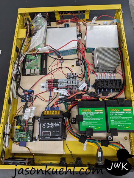
I then decided to do a tad bit of future-proofing and added two different 12-volt inputs into the same DIN rail. I did a lot of tossing back and forth to figure out how I wanted to control the power from those two different 12-volt sources. After a bunch of mucking around and asking friends at my local maker space, I decided to take the physical way and move a fuse. In the picture above, on side A there is one 5 amp fuse in on side B there is one 5 amp fuse. If I decide to move away from 120 volts 12V inverter to a straight 12 volts, I can do that by just physically moving the fuse.
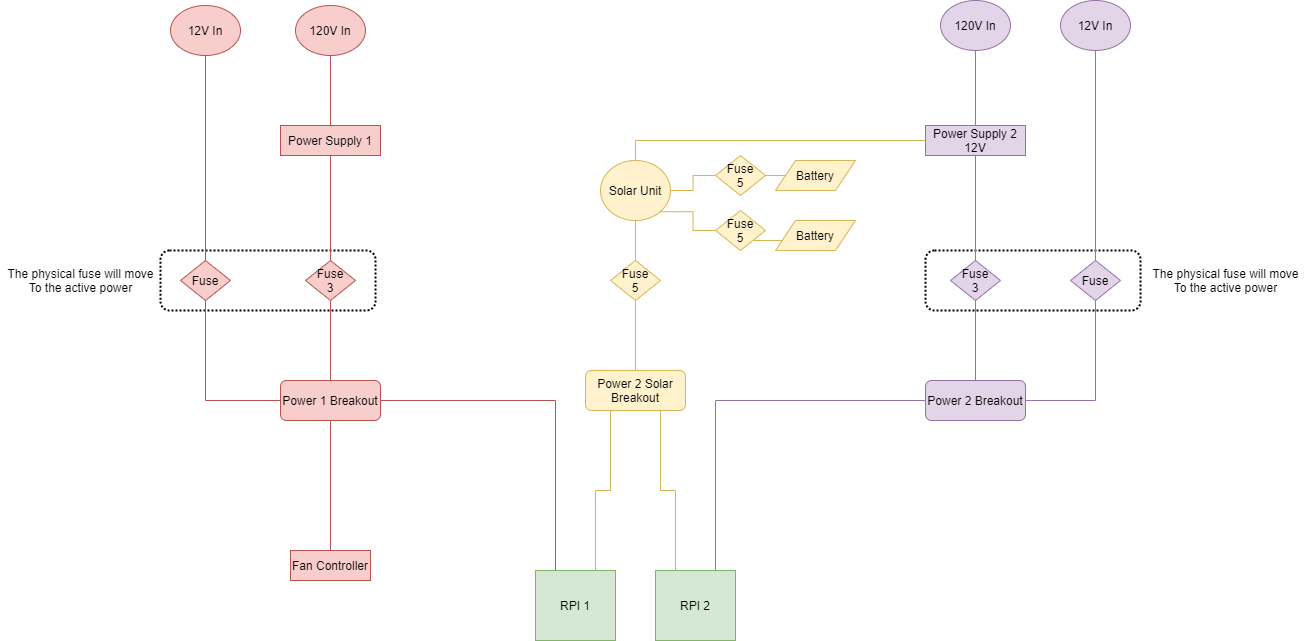
As you can see in the diagram above, everything is well-marked and labeled, but the same thing will have to be done on the inside of the case. There is still a bunch of custom 3D printing I need to do to be highly visible.
Internal Layout
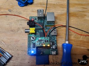
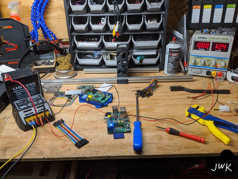
After I got my bearings on how things will look, I had to do a bunch of internal cleanups. It looks so pretty and clean now!
During this cleanup, however, I encountered a problem. I found out that when the Pi was on battery, the Raspberry Pi module was feeding power back to the 12-volt inverter (Merrp). This wasn’t causing any immediate problem but the LED indicators told me that it had power on both A-side and B-side. This means it was sending energy back to the inverter, and it thought it had a 12-volt power source on the output side. To fix this, I’m adding a MOSFET to control the direction of power. There will be two MOSFET’s on the 12-volt inverter side to prevent this from happening further. However, that will be for version 2.
Making Sure It Modular.

I knew that I wanted to be able to unhook these Pis if I had to but also wanted the connections to be rock solid. I don’t know the reason currently, but better safe than sorry on a 2+ year adventure. It’s why I picked using the old 4-pin at/atx/ide power cables I had a surplus of old power supplies, and it made sense for what I was doing. If I needed to I can add external power to Pi and remove them from the case.
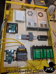
Version 1 Complete
It took a long time to finalize the design of version 1, but this is basically how I wanted things to look:
- Two fans front and back to flow air over the Raspberry Pis
- An internal solar controller for the battery backup.
- Two inverters of the same type (I was having issues before with inverters that were not the same. It either had voltage issues or all-around quality issues. I started talking to a couple of my friends that did Industrial Automation in factories for a living to get some input from them and see what they use.(They also helped you ID my power issues above. Thank you, Andrew))
- As you can also tell, the wiring is a complete mess. This is also changing. I will be putting cable trays inside here to go through in nicely put all the cables so things like a bit neater.
The concept of this works. It just needs a little more work, and I can finally get this thing online. The start date is January 1st, 2021. The Raspberry Pis will be doing a web version of Doom so people can play Doom on this little device. My goal is to have this entire project started and going by the first minute of 2021. I will be so unhappy if something power-wise does happen and fail; however, that’s how we learn to make things better.
As for the Raspberry Pi 3, I haven’t decided what it will do yet, and I’m looking for ideas.
Components And Cost
MEAN WELL EDR-120-12 Single 12V 10 Amp 120W $29.66 – 2
Din rail With Terminal Blocks $26.99 – 2
2000 Cycles 12V 6Ah Battery $29.99 – 2
Fan Controller $7.99 – 1
Fuse Block $8.69 – 1
MoPi-Hat PI1 $39.95 – 1
MoPi Hat PI2 $38.44 – 1
Things I Had But Still Cost Money
Old Google Server
IEC Ends
RJ45 female ends.
Raspberry Pi 3
Raspberry Pi 1
Cables
Old Power Supplies
If you have any input or see an issue with my overall design, please feel free and message me directly.


